Ethernet wiring & color codes.
A practical reference for T568A and T568B wiring, with the original diagrams from our CAT5 guide.
T568A and T568B at a glance.
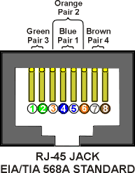
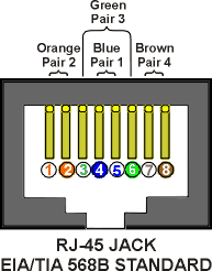
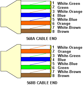
These two wiring schemes assign the four twisted pairs to connector pins. The table below lists pin numbers explicitly; match the connector manufacturer's pin labels and viewing orientation when terminating a cable.
| Pin | T568A | T568B |
|---|---|---|
| 1 | White / green | White / orange |
| 2 | Green | Orange |
| 3 | White / orange | White / green |
| 4 | Blue | Blue |
| 5 | White / blue | White / blue |
| 6 | Orange | Green |
| 7 | White / brown | White / brown |
| 8 | Brown | Brown |
Straight-through or crossover?
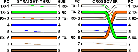
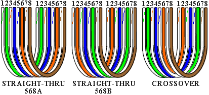
For straight-through cabling, use the same scheme at both ends: T568A to T568A, or T568B to T568B. Follow the scheme already used in your installation.
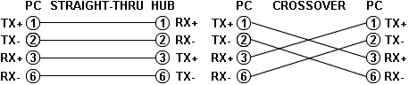
A T568A-to-T568B cable swaps the transmit and receive pairs used by older 10/100 Ethernet interfaces. Many modern Ethernet ports support auto-MDI-X and automatically accommodate either arrangement. Check the equipment documentation before choosing a crossover cable.
The crossover diagrams below describe legacy two-pair Ethernet connections. They are historical references, not a universal crossover specification for every Ethernet speed or device.
Before you put a cable into service.
- Match the wiring scheme used by your patch panels and outlets.
- Follow the connector manufacturer's termination instructions.
- Test the completed cable and label both ends.
- Use the equipment documentation to confirm cabling requirements.
For help with network design or troubleshooting, explore our IT consulting and infrastructure services or contact DC Current LLC.